C4D Headphone

My texture work in 2021, modelling by SOM.

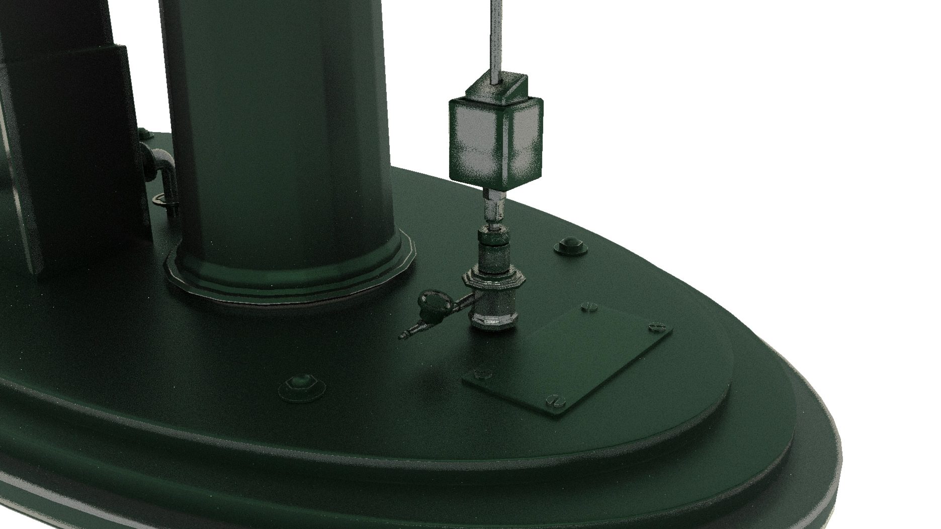
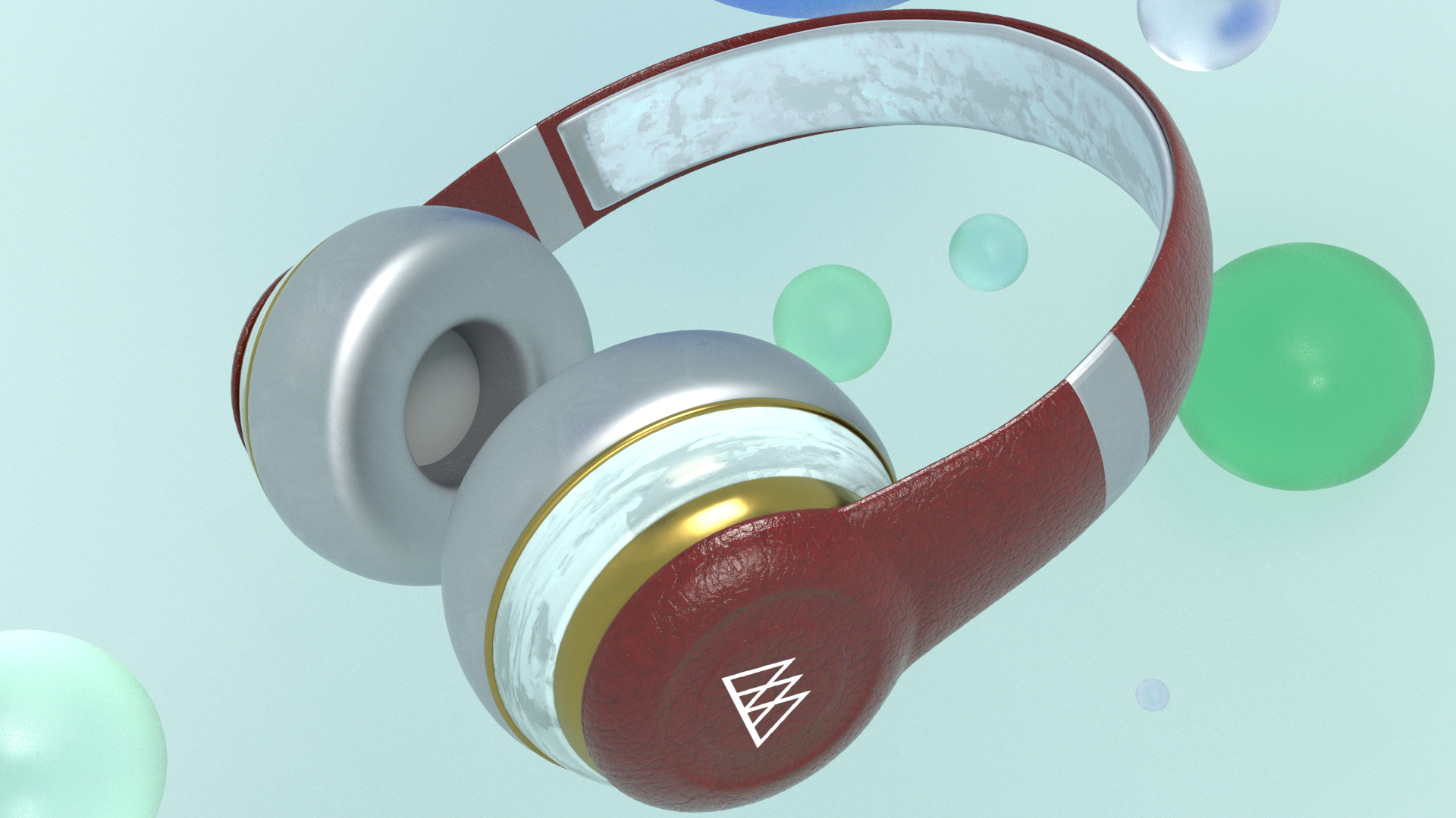
Here is a self assignment I started at online course held by School Of Motion before studying in LCC, I used Cinema4D to add texture and render with Redshift.

Recently, I tried to redo this self assignment, as I think what I’ve learnt from recent Maya class, can be applied the same principles into Cinema4D. For instance, adding noise to make imperfect edges, bump map and displacement map for realistic texture.

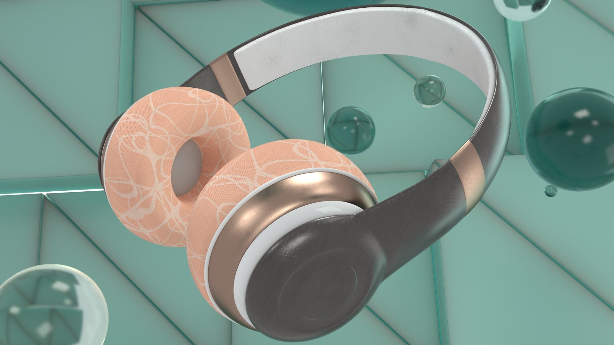
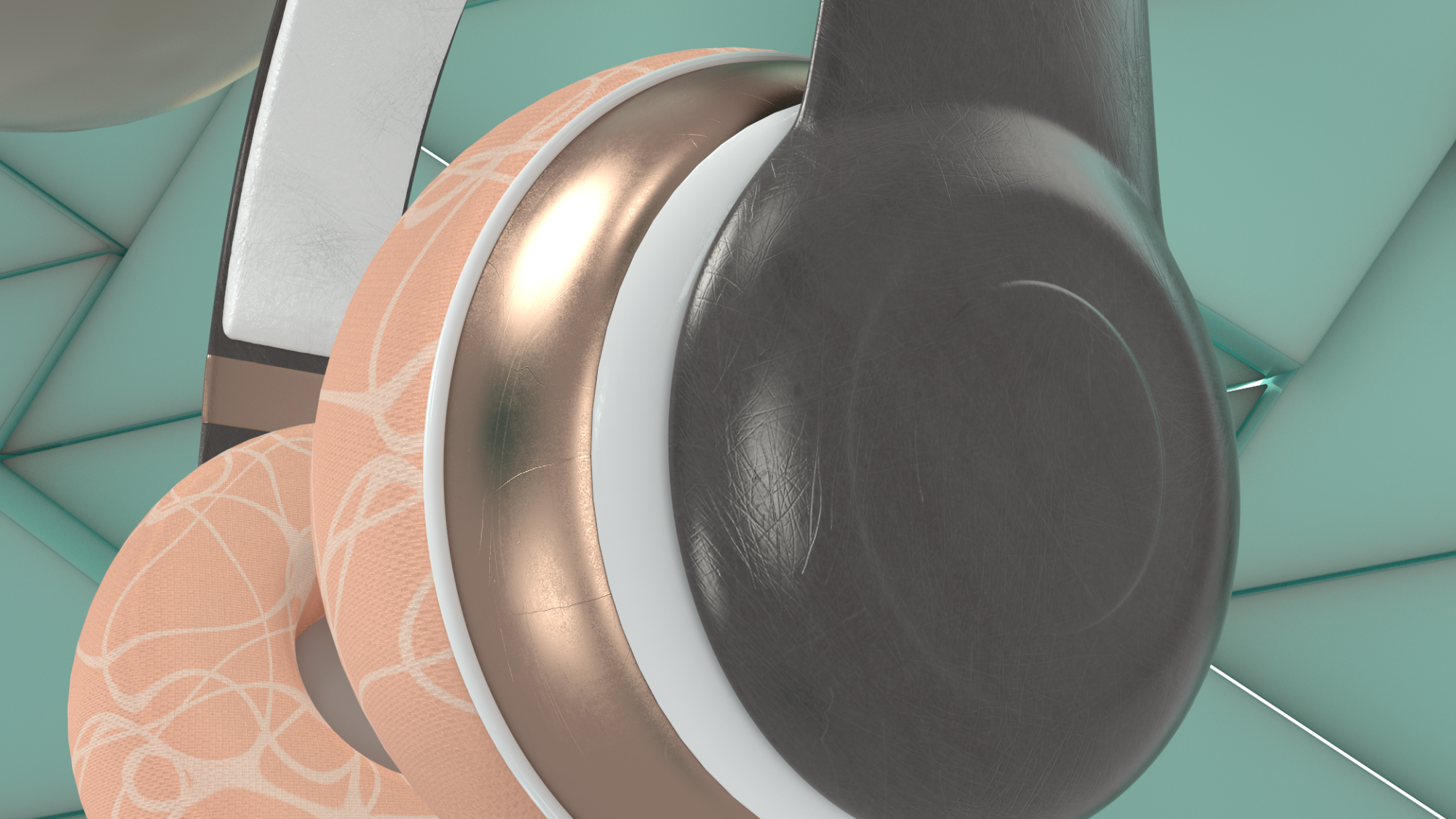
Scratched texture on cooper and plastic headphone surface.

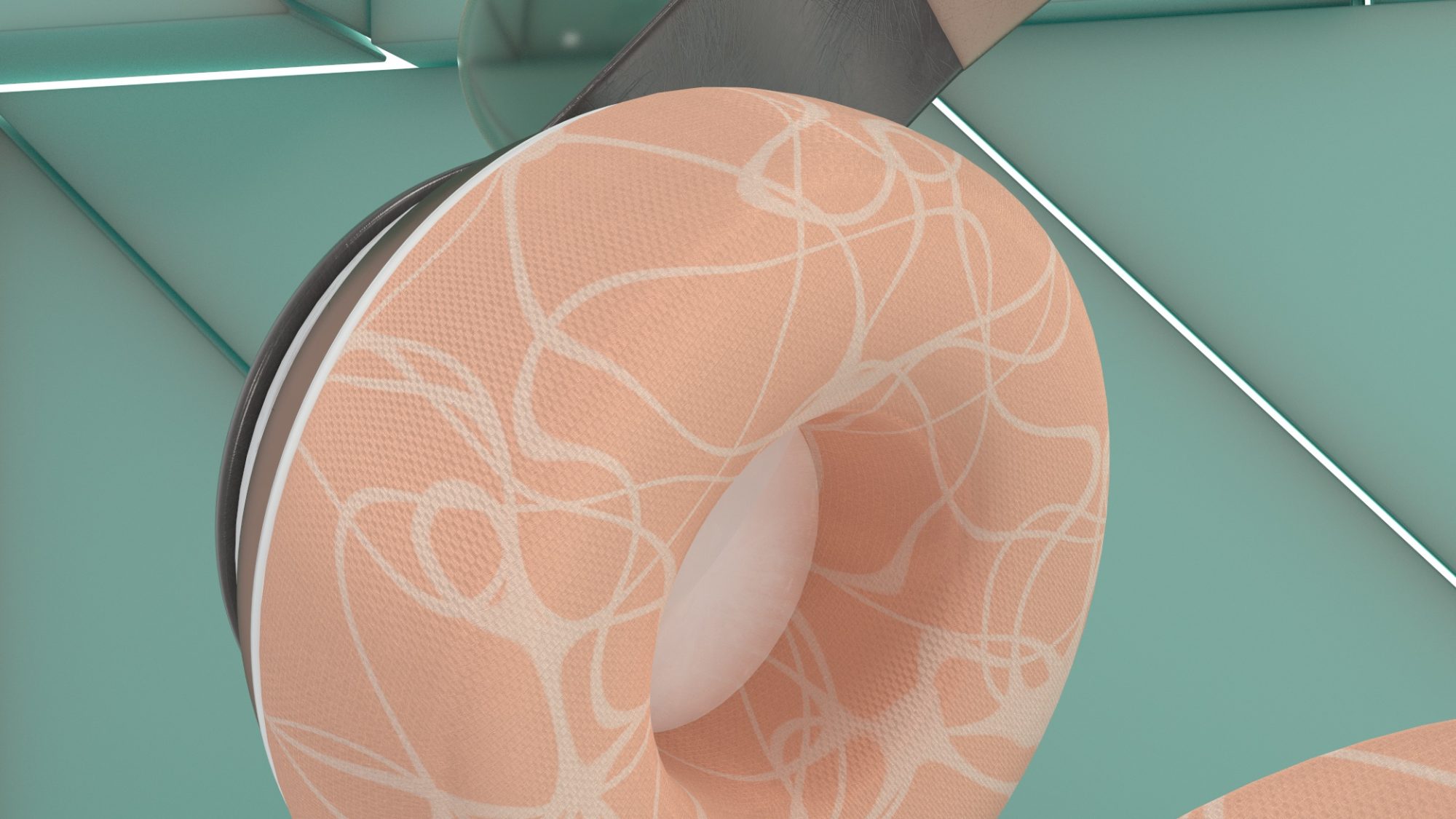
Cozy feeling with fabric bump map for the ear bud area.

Overall, the result with Redshift is quite satisfying , quick responds in rendering, convincing material reflection and user-friendly interface. As a VFX students, it is always beneficial to try to work on various 3D software, to understands their pros and cons.

Week 05 UV and Texture

There are two types of material I used, they are both come from material source greenpaint and sliver_body. On the other hand, I added some aiNoise for aiCurvature for the object edges. Then I blended all materials with linking to two aiMixShader. First result is a greenpaint as the main compound with silver edges, and second one is the opposite one.

The result is quite satisfying. Of course, I supposed to do more detail adjustments on each parts of all gears to have a even better result. And I haven’t add any texture and bumpmap yet, probably I will do it later with lighting adjustment as well, while the object is put in scene. I think the reflection is too smooth and flawless at this stage.

Week 04 Motion Design

Actually, not much keyframing in this project, as it is inefficient to animatic every parts of the engine each by each. Most of the motion can be controlled by rigging and node graph for linking up all tiny parts.

For example, using node graph to link rotation of two gears.
The main and side gear one are designed to rotate clockwise, while the other one is anti-clockwise.

Other gears are using the same principle as well. Or just simply make it parent to another objects.

Here is another example for showing how I use rigging and node graph, instead of keyframing to do the motion.

With graph editor, motion of this arm should be more “industrial” with stronger force and heavy mechanic feeling. Comparing the two motions as below, I prefer the 2nd version with more dramatic feeling.


Final Motion Design

Week03 Production Timeline

After 1on1 tutorial with our course leader, Christos this week, we have to prepare a presentation to him to share our story and work in progress.

In this week, I’ve received a production timeline as well. It showed that each job position and expected time period.

With this tight schedule, it showed the transparent of what everyone is doing, which is a must for us as a team to work on. Our shots were all renamed into a series of code name, which are easier for us to communicate and name our files properly.

In this week, as a compositor, my workload is not quite heavy in recent, I spent some time to study CG compositing on YouTube Channel, Hugo’s Desk, as a warmup for my tasks in near future.

I think Hugo’s Desk is a great platform for me to learn some extra techniques as a bonus, together with my regular Tue Nuke classes.

Week 02 animatic

As a compositor in this collaborative unit, I’ve received an animatic from our director, Chad, in week 2 . It is useful for the whole team to preview a rough direction in preproduction period.

Also, we have a greeting for everyone in this team to say a hi to each other by online.

After reviewing this animatic, I was worried about the duration, as it is a animation with lots of message to tell. And perhaps that’s an overestimated project for such a emotional story, as it weighted quite a huge pressure to join this team for collaborative project. With showing my concerns to our director, Chad comforted me with a load of encouragement, which I definitely need it.

WK 02 Remove Markers

Among all kinds of methods to remove markers, personally I think Inpaint did the best result in this shot. Inpaint is similar to Unpremult and Premult, but it helps a lot to add back details on patches.


I selected frame 1013 to do a framehold , but maybe it is not the best options for this shot. As I can still see some circular shapes on the face, while the actor turned his head.

And there are differences for me to turn off the default selection on graphic card in rendering SmartVector. This in turn, allow the result got less error distortion.

05 | 2D Panel tracking

Result


Work In Progress

In Nuke, the 2D panel tracking is user friendly for everyone to apply the tracking. However, the most time-consuming part for me is the use of my organising skill for the node graph in Nuke. Which go which, where and where link together, etc… And the prioritization for each steps were quite confusing at first. It might seems an easy task with 2D panel tracking, but when it came with clear up and color matching. It was not easy anymore to put separated tasks into one single script. Fortunately, I eventually overcame it in my own way, but I hope it is able to reach the industry standard for other compositors to understand my node graph.

Nuke node graph for this 2D tracking

Week03 Rigging

This week, I have learnt how to do a simple rigging with locators and constraints. Only using one keyframe, all the motions seem convincing with rigging.

Also, I have learnt to animatic the texture on the object instead of the object itself, to create a belt conveyor. It is convincing to trick the eyes of audience that the belt conveyor is moving.

Then, same principles applied to my own engine. The U-shape objects has to always pointed to the hexagon gear, no matter it goes ups and downs. Therefore, a locator is set at the gear centre, which then U-shape is constrained to the movement of the gear.

Wk01,02 Idea And Modelling

Benson’s Vertical Engine

First of all, I would like to make it clear. I know nothing about engineering. Zero knowledge. None of it. However, when I research on steam engine. I saw this Benson’s Vertical Engine looks so cool with its vintage design. I just hooked by its appearance.

According to pollymodelengineering.co.uk,

“This type of engine was called by the Victorians a vertical engine. An engine with the cylinder above the crankshaft was called an inverted vertical. This engine was built in the middle of the nineteenth century and is typical of the type.

The good thing is I can always search for tons of reference for this engine as it is a object physically existed :

Work In Progress

Afterthat, I built models to follow all details parts with my reference photos. Again, I still don’t understand how it function, but I decided not to dig into it. I just adjusted my models by my own visual adjustment.